Welcome to my Website!

This site will contain my project to work out how a flip dot display works.

This flip dot display used to live in a bus and now lives in my house. It was designed and manufactured by Hanover Displays who have been making displays for transport since 1995.
It is a 28x8 grid for a total of 224 dots.
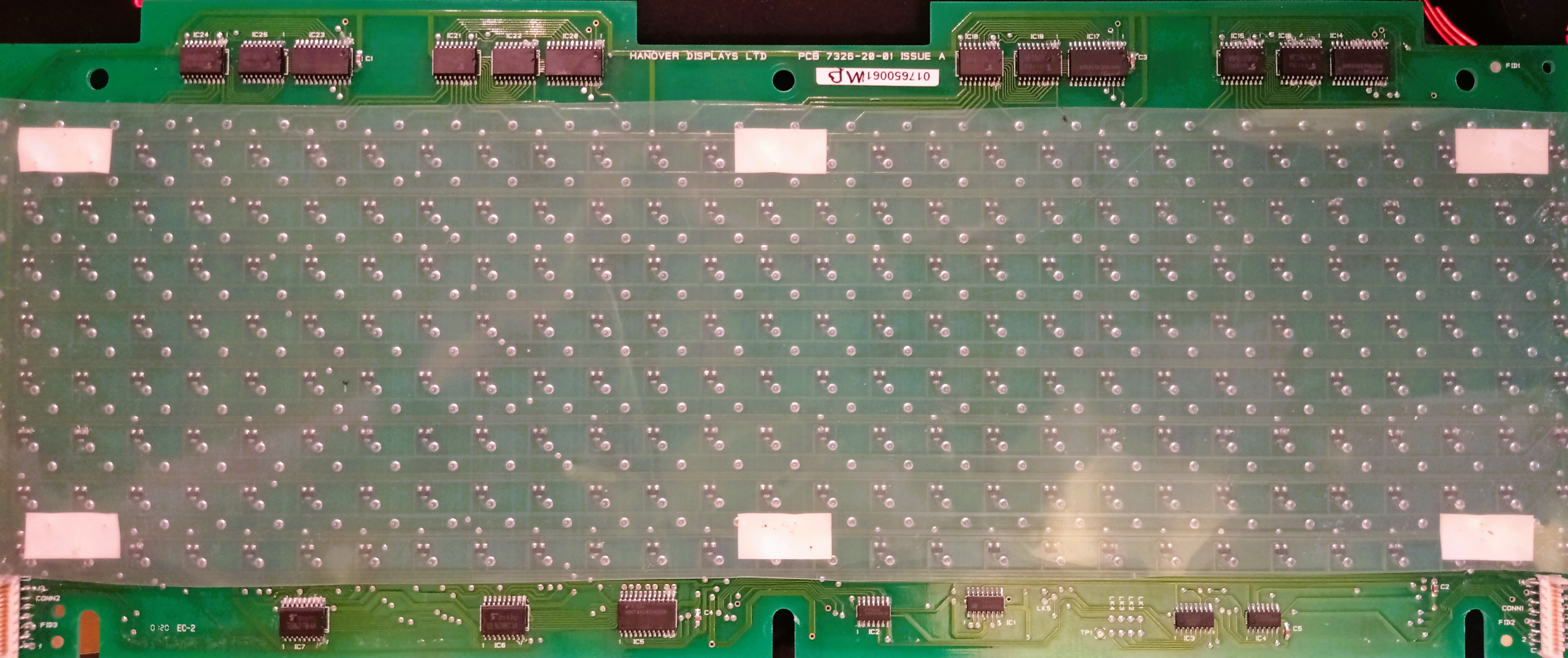
ICs 23/24/25 - Addressing Columns
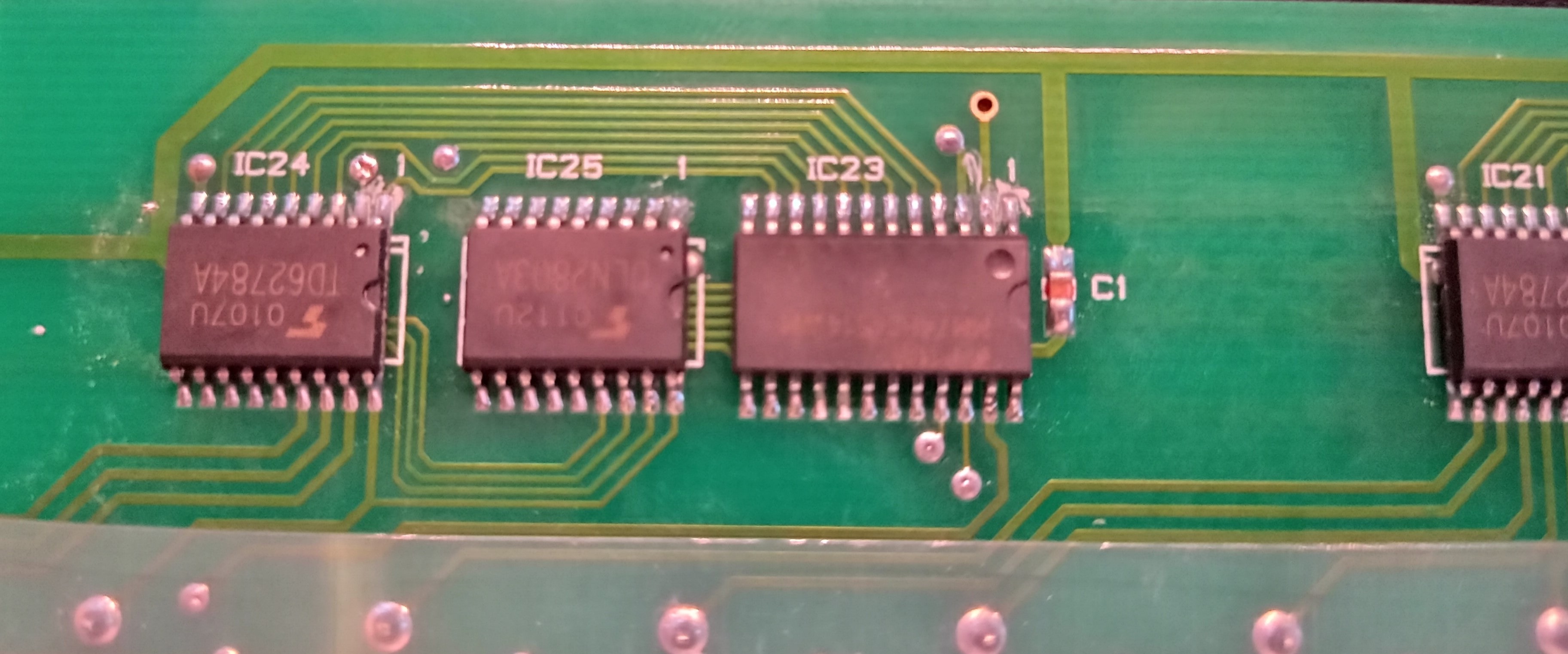
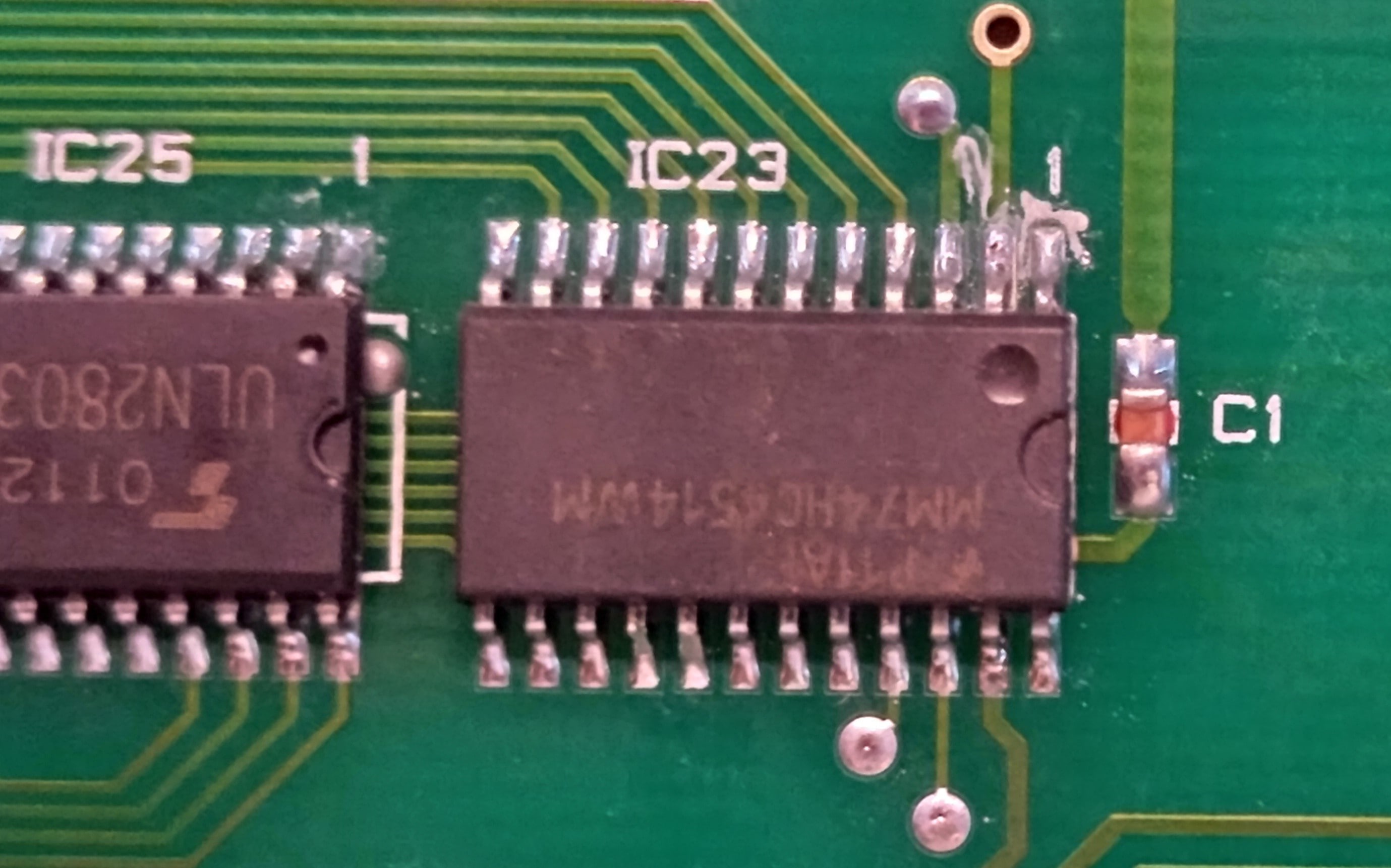
IC23 is a P11A/MM74HC4514WM (datasheet).
It is a multiplexer, which allows only 4 bits of input to set one of 16 outputs to high (with the rest of them staying low).
IC24 is labelled 0107U/TD62784A (datasheet). This is a high voltage source driver, which allows 8 low-current inputs to control 8 high-current outputs. All of these chips on the board together have 28 connected output pins that line up with the top of the columns of dots.
IC25 is labelled 0107U/ULN2803A (datasheet). This is a Darlington transistor array. This chip is similar to IC24, also allowing 8 inputs to control 8 high-current outputs, however this chip also has clamping diodes which allow it to control inductive loads (such as the coils in a flip dot) without risk of damage to the chip due to inductive kickback. The outputs of ICs 24 and 25 are connected - maybe one is used to turn the flip dots on and the other is used to turn them off? (By powering the coil with current flowing in each direction, with one chip controlling each direction).
ICs 5/6/7 - Addressing rows


ICs 5, 6 and 7 are again the MM74HC4514WM, ULN2803A, and TD62784A. Given that there are 8 rows that need to be drivable in both directions, these likely control those, but its hard to see how/if these are connected due to the number of vias used to connect them, and parts of these circuits go under the flip dots.
ICS 1/2/3/4 -
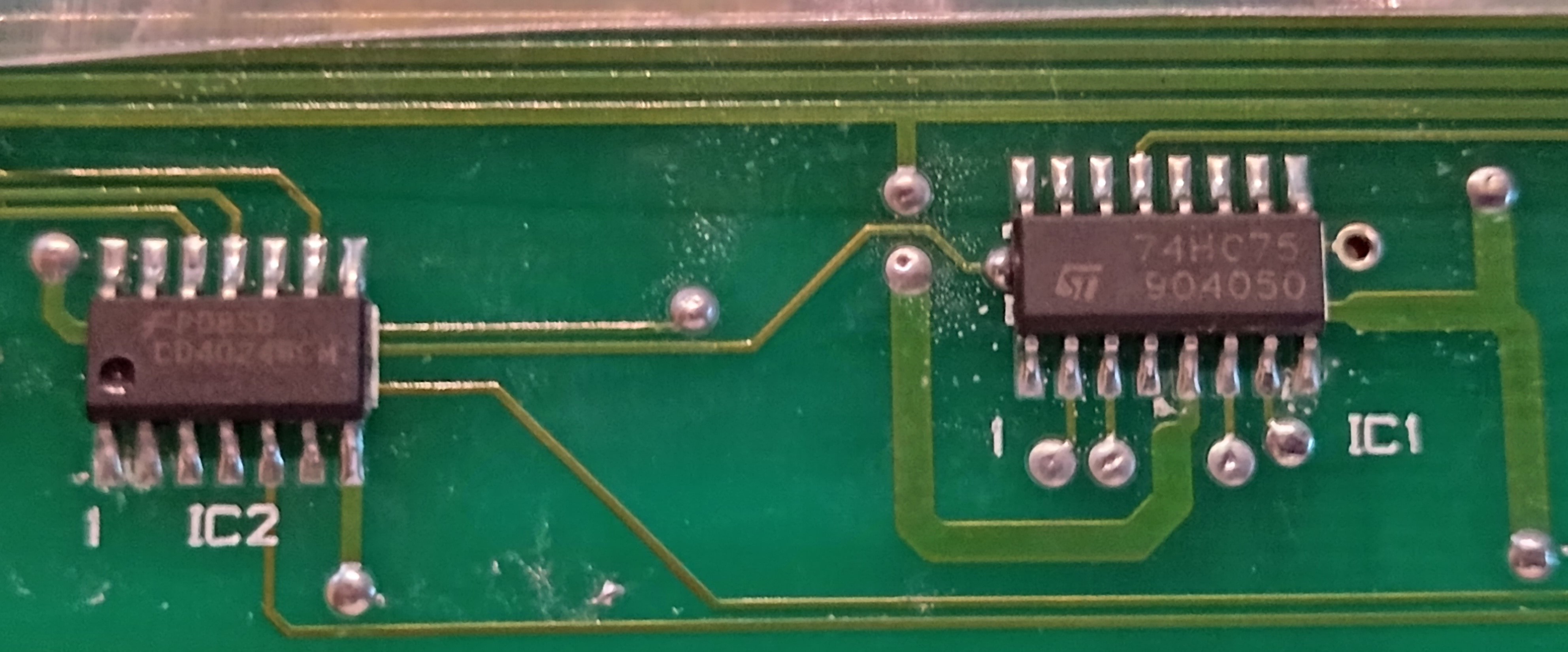
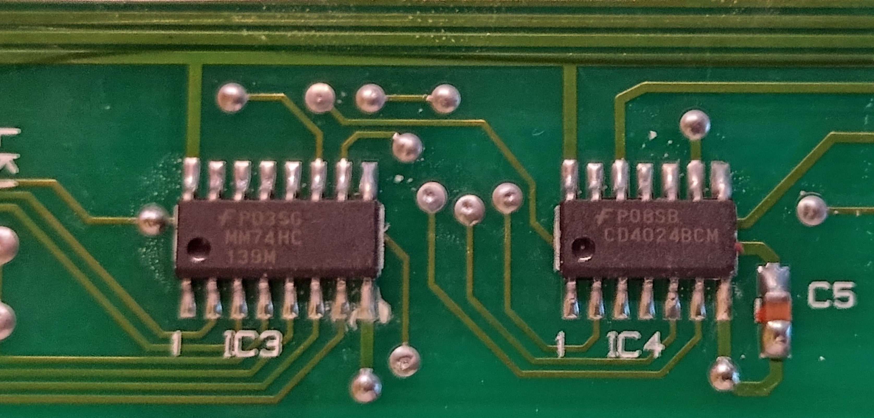
IC 1 is labelled 74HC75/904050 (datasheet). This is a quad bistable transparent latch, which can store and output 4 bits of information (and their negations).
ICs 2 and 4 are labelled P08S8/CD4024BCM (datasheet). This is a 7-stage ripple carry binary counter.
IC 3 is labelled P03SG/MM74HC/139M (datasheet). This is a dual 2-to-4 line decoder. It lets you pull one output pin to low selected by two input pins.
Connectors
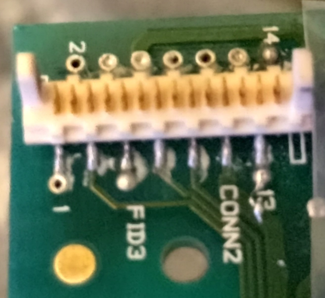
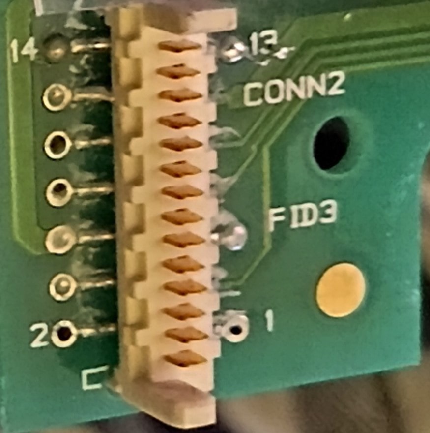
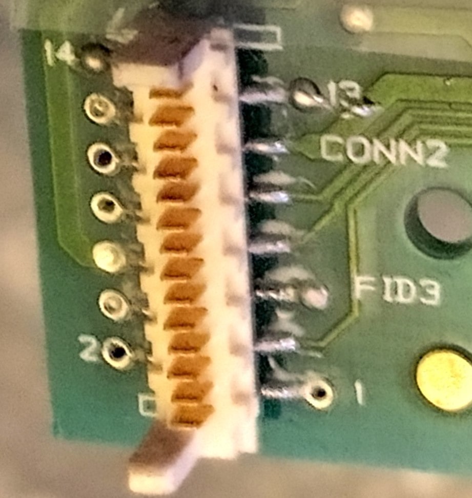
This is a 14 pin Molex Picoflex connector for attaching a ribbon cable (part no 90814-0214, product info). Luckily these connectors and ribbon cables are still available, so I can just order some of these for the driver board and a ribbon cable with matching connections.
Schematic
Now that all of the important components are identified, I've made a schematic. There are a lot of vias, so I ended up using multimeter to trace many of the connections.

Pin 11 is used for power, and pins 6 and 1 both connect to ground (they are connected, bizarrely).
Pins 7-10 and pin 2 are where things get interesting. These control which flip dot in the grid will receive a pulse of power to change it, but not directly. The board has a small state machine made up of two binary counters. Pins 7-10 are set to contain a change to be made to the state machine, and pin 2 going from high to low sets the quad latch to those values.
